To to able to extend wings, I have chosen to use 4-wired Stepper Motors.
For mechanical design, look into Wings Mechanism.
Types of Stepper Motor
6-wired Stepper Motor
Stepper Motors are controlled by Pulse-width Modulation on multiple (4) wires.There are different approaches how to control a Stepper Motor.
-
Wave drive
1 phase on at a time
Easiest to understand. Pulse on one wire is followed by pulse on second in desired direction. -
Full-step drive
2 phases on at a time
Same as Wave drive but next pulse starts in middle of previous one.
Thanks to this, we can group wires by two where on of them is 1 and other 0 (which will we use for 4-wired Stepper Motor).
Wave drive
"Wave drive" is way to control Stepper Motor by activating one of its magnet (wire) at a time.
Let's start with code for Arduino.
First we need to define output pins (I recommend you to not connect Stepper Motor directly to Arduino).
#define PIN_0 0
#define PIN_1 1
#define PIN_2 2
#define PIN_3 3

void setup()
{
  pinMode(PIN_0, OUTPUT);
  pinMode(PIN_1, OUTPUT);
  pinMode(PIN_2, OUTPUT);
  pinMode(PIN_3, OUTPUT);
}
This gives us 4 pins to use for output so our "magic" can begin.
byte stepId = 0;
int pins[] = { PIN_0, PIN_1, PIN_2, PIN_3 };
First of all we need a variable to store which pin is currently active. We also create array of pins which allows us to use
stepId as index into the array to get current active pin.| stepId | PIN_0 | PIN_1 | PIN_2 | PIN_3 |
|---|---|---|---|---|
| 0 | HIGH | low | low | low |
| 1 | low | HIGH | low | low |
| 2 | low | low | HIGH | low |
| 3 | low | low | low | HIGH |
bool directionRight = true;To be able to change rotation direction, we need a variable for it. For our purpose,
true / 1 / right is one direction, false / 0 / left is second direction. The rotation is virtual for us because it depends on order of your wires.void performStep()
{
// Disable previous output
digitalWrite(pins[stepId], LOW);
// Loop stepId from 0 to 3 in both directions
if(directionRight)
{
stepId++;
if(stepId == 4)
stepId = 0;
}
else
{
stepId--;
if(stepId == -1)
stepId = 3;
}
// Enable current output
digitalWrite(pins[stepId], HIGH);
}Now we can proceed to actual code. It will be best (for clarity) to create function to perform a rotation step.
In this function, we need to disable previous output pin and enable next. We can disable all pins and then enable only the wanted one but I have chosen different approach which is less code to run (but will create "blank time" with no pin on
HIGH).When using C approach instead of Arduino's
digitalWrite, we may write 1 << stepId into target port. It means to "read" current port output, "clear" first (lowest) 4 pins (port & 0b11110000) and replace them by new value (and write into port: port = (port & 0b11110000) + (1 << stepId)).The math in between is simple. For increasing (right) direction, when we reach 4 (last valid value is 3) then we loop back to 0. For decreasing (left) direction, when we reach -1 (last valid value is 0) then we loop back to 3.
We can use % (modulo) operation but it is "safe" only for non-negative numbers (0 and above) because its implementation for negative numbers may differ (some implementations return negative values for negative values but we only want values usable for our
pins array).void loop()
{
performStep();
delayMicroseconds(500);
}Last thing needed is to write down a
loop() function which will be repeatedly called. The delay is 0.5ms (0.0005s) which means 2 000 steps per second (1 divided by delay in seconds).You can imagine it as a triangle where 1 is at the top and steps and delay are on the bottom edge. It means 1 = steps * delay and steps = 1 / delay and delay = 1 / steps. With this in mind, you can calculate the delay yourself.
Whole code:
// Pins which we will use
#define PIN_0 0
#define PIN_1 1
#define PIN_2 2
#define PIN_3 3
void setup()
{
// Set pins as Output
pinMode(PIN_0, OUTPUT);
pinMode(PIN_1, OUTPUT);
pinMode(PIN_2, OUTPUT);
pinMode(PIN_3, OUTPUT);
}
// Current step (0-3, 4 total)
byte stepId = 0;
// Array of pins to get current active pin
int pins[] = { PIN_0, PIN_1, PIN_2, PIN_3 };
// Variable to define rotation direction
bool directionRight = true;
void performStep()
{
  // Disable previous output
  digitalWrite(pins[stepId], LOW);

  // Loop stepId from 0 to 3 in both directions
  if(directionRight)
  {
    stepId++;
    if(stepId == 4)
      stepId = 0;
  }
  else
  {
    stepId--;
    if(stepId == -1)
      stepId = 3;
  }

  // Enable current output
  digitalWrite(pins[stepId], HIGH);
}
void loop()
{
// Perform next rotation step
performStep();
// 0.5ms
// delay(0.5)
// 2 steps per 1ms
// 2000 steps per 1s
delayMicroseconds(500);
}
Full-step drive
The code will be mostly similar to Wave drive. We need the same pins and samestepId loop. The only difference is in enabling 2 pins at a time.Yes, after first step there will be only one pin (
PIN_1) on HIGH but there is no problem with it.| stepId | PIN_0 | PIN_1 | PIN_2 | PIN_3 |
|---|---|---|---|---|
| 0 | HIGH | HIGH | low | low |
| 1 | low | HIGH | HIGH | low |
| 2 | low | low | HIGH | HIGH |
| 3 | HIGH | low | low | HIGH |
This means we will still disable previous output pin and do the math but instead enabling current output, we will enable the next one.
digitalWrite(pins[(stepId + 1) % 4], HIGH);Index of next pin is not
stepId + 1 because it may get us out of range of array (when stepId is 3, then stepId + 1 is 4 which is out of bounds. There are two ways to fix this.The mathematical one is to use % (modulo) operation (as shown above) to limit the index to be from 0 to 3 (no need to care about negative values). It is really simple approach but we want something faster (because this means we need to calculate it all the time).
The programmer approach is by adding
PIN_0 as 4th item of pins array (we are not using length of the array because we did not think it would change and it is good (useful) for us now). Thanks to this, we can remove % (modulo) while keeping stepId + 1. Our stepId will still loop from index 0 to 3 (pins 0,1,2,3) but stepId + 1 will loop from index 1 to 4 (pins 1,2,3,0) which is exactly what we want.Whole code:
// Pins which we will use
#define PIN_0 0
#define PIN_1 1
#define PIN_2 2
#define PIN_3 3

void setup()
{
  // Set pins as Output
  pinMode(PIN_0, OUTPUT);
  pinMode(PIN_1, OUTPUT);
  pinMode(PIN_2, OUTPUT);
  pinMode(PIN_3, OUTPUT);
}

// Current step (0-3, 4 total)
byte stepId = 0;
// Array of pins to get current active pin
// stepId     ~ { PIN_0, PIN_1, PIN_2, PIN_3 }
// stepId + 1 ~ { PIN_1, PIN_2, PIN_3, PIN_0 }
int pins[] = { PIN_0, PIN_1, PIN_2, PIN_3, PIN_0 };

// Variable to define rotation direction
bool directionRight = true;

void performStep()
{
  // Disable previous output
  digitalWrite(pins[stepId], LOW);

  // Loop stepId from 0 to 3 in both directions
  if(directionRight)
  {
    stepId++;
    if(stepId == 4)
      stepId = 0;
  }
  else
  {
    stepId--;
    if(stepId == -1)
      stepId = 3;
  }

  // Enable next output
  digitalWrite(pins[stepId + 1], HIGH);
}

void loop()
{
  // Perform next rotation step
  performStep();
  // 0.5ms
  // delay(0.5)
  // 2 rotations per 1ms
  // 2000 rotations per 1s
  delayMicroseconds(500);
}
4-wired Stepper Motor
For 4-wired (Bipolar) Stepper Motor, we need to use H-Bridge (used to control rotation direction of DC motors) for both electromagnet. You can look at StackExchange where it is well described (I will still try my best).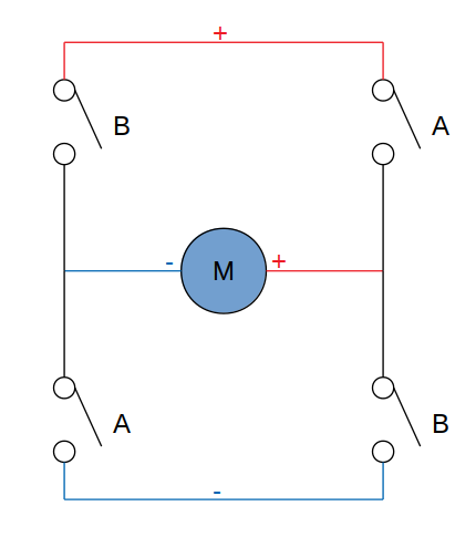
Principle of H-bridge is simple - exactly 2 "switches" are enabled at a time (both with same label on image above). Only difference is that you need to use 2 bridges (one for each pair of wires).
Sou can simulate H-Bridge on Falstad.com where I made the scheme for you. The 2 switches act as Arduino Outputs (inner state is
HIGH and outer state is LOW).Order of wires / pins is:
- A from 1st H-bridge
- A from 2st H-bridge
- B from 1st H-bridge
- B from 2st H-bridge
Reverse Rotation
To reverse rotation, change order ofpins array.int pins[] = { PIN_0, PIN_1, PIN_2, PIN_3, PIN_0 };
int pins[] = { PIN_3, PIN_2, PIN_1, PIN_0, PIN_3 };Controlling by "Target Step"
Target Step Id
In this case, we will consider start step (when switched on) to be 0. WhendirectionRight is true then total steps are increasing, otherwise decreasing (same as stepId without loping).We already have
performStep() function with has same name and purpose in both Full-step drive and Wave drive.bool directionRight = true;
int currentStepId = 0;
int targetStepId = 0;
bool done = true;We already have
directionRight but we will need something more - the limit. The limit is created by 3 variables - currentStepId which can be used to calculate stepId (stepId = currentStepId % 4 when modulo returns only >= 0 values), targetStepId which we will compare to currentStepId and save it to done (to reduce calculations).void changeTargetStep(int targetStep)
{
done = targetStep == currentStepId;
if(done)
return;
targetStepId = targetStep;
directionRight = targetStepId > currentStepId;
}First of all we need a function (which will be later called when we implement Communication) to change target step and by it rotation. Direction is decided easily -
directionRight is true when increasing currentStepId towards targetStepId.The
done should be last for multi-thread processors but because we have only one thread, we can place it first and (again) reduce calculations (why not when we can).We also need to add condition to not perform steps when we are already on target step. It can be done by adding the condition (code below) at start of
performStep. if(done)
return;Or by checking before calling
performStep();. if(!done)
performStep(); stepId++;
currentStepId++;
stepId--;
currentStepId--;We also need to change
currentStepId same way we change stepId. That means we replace stepId++; and stepId--; by code above (respectively).done = targetStepId == currentStepId;At the end of
performStep(), we need to check if we are done. if(done)
{
digitalWrite(PIN_0, LOW);
digitalWrite(PIN_1, LOW);
digitalWrite(PIN_2, LOW);
digitalWrite(PIN_3, LOW);
}And last piece of code to add into
performStep() is disabling all pins. Yes, we can disable current (pins[stepId]) and next (pins[stepId+1]) pins but settings all (our) pins to LOW should be faster (and allow compile-time optimization).In C, we can set all pins to 0 by
port = port & 0b11110000If you went for Wave drive then you don't need you reset all pins but only to not set current pin. It is done by adding
digitalWrite(pins[stepId], HIGH); (make sure it is after changing value of done).In our case we are using Worm Gear to transfer motor rotation into movement of wings. Because of this, we don't need to power it when it stops rotating because Worm Gears work in one direction. If you have different mechanism (or directly connected) then you may need to keep powering the last pin (only one to not make them fight) or even consider adding mechanism to check rotation and rotate against it in order to keep same rotation angle on output.
Whole code:
// Pins which we will use
#define PIN_0 0
#define PIN_1 1
#define PIN_2 2
#define PIN_3 3
void setup()
{
// Set pins as Output
pinMode(PIN_0, OUTPUT);
pinMode(PIN_1, OUTPUT);
pinMode(PIN_2, OUTPUT);
pinMode(PIN_3, OUTPUT);
}
// Current step (0-3, 4 total)
byte stepId = 0;
// Array of pins to get current active pin
// stepId ~ { PIN_0, PIN_1, PIN_2, PIN_3 }
// stepId + 1 ~ { PIN_1, PIN_2, PIN_3, PIN_0 }
int pins[] = { PIN_0, PIN_1, PIN_2, PIN_3, PIN_0 };
// Variable to define rotation direction
bool directionRight = true;

int currentStepId = 0;
int targetStepId = 0;
bool done = true;
void performStep()
{
  if(done)
    return;
// Disable previous output
digitalWrite(pins[stepId], LOW);
// Loop stepId from 0 to 3 in both directions
if(directionRight)
{
    stepId++;
    currentStepId++;
if(stepId == 4)
stepId = 0;
}
else
{
    stepId--;
    currentStepId--;
if(stepId == -1)
stepId = 3;
}
// Enable next output
digitalWrite(pins[stepId + 1], HIGH);
done = targetStepId == currentStepId;
if(done)
{
//digitalWrite(pins[stepId], LOW);
//digitalWrite(pins[stepId + 1], LOW);
digitalWrite(PIN_0, LOW);
digitalWrite(PIN_1, LOW);
digitalWrite(PIN_2, LOW);
digitalWrite(PIN_3, LOW);
}
}
void changeTargetStep(int targetStep)
{
// Check if we need to change values
done = targetStep == currentStepId;
if(done)
return;
targetStepId = targetStep;
// right / true = increasing currentStepId
directionRight = targetStepId > currentStepId;
}
void loop()
{
// Perform next rotation step
performStep();
// 0.5ms
// delay(0.5)
// 2 rotations per 1ms
// 2000 rotations per 1s
delayMicroseconds(500);
}
Percentage of Range
We are currently usingint (which is int16 on ATMega base boards). But with it, we need to know specific step on which we target.To use float with range from 0.0 to 1.0 (including both values). To do so, we need to know our limits.
Let's say that we have
stepMin and stepMax as our limits and target as our range (0.0 to 1.0). With this in mind, we calculate target step byint stepRange = stepMax - stepMin;
targetStepId = stepMin + (int)(target * stepRange);But what to do when we don't know the limits? Or at least don't know them relatively to our start step.
Because of this, we will consider
stepMin to be 0 and stepMax to be maximum value of int (32767).How can I know that 0 is minimum? Why the maximum value?
Well, I don't know but we can add microswitches as our limits and when our input is
0.0 or 1.0 then we keep rotating until we reach a microswitch.#define PIN_MIN 4
#define PIN_MAX 5First of all, we need to define our pins for microswitches...
pinMode(PIN_MIN, INPUT_PULLUP);
pinMode(PIN_MAX, INPUT_PULLUP);...and set them as Input. Because we use switches connected only to the ground (on the other side then Arduino), we need to use
INPUT_PULLUP because we don't our input to act as an antenna when the switch is not pressed (for more info, look at description of Arduino's Digital Pins).This will also cause our input to be inverted (
LOW when pressed). if(!done)
{
if(directionRight)
done = digitalRead(PIN_MAX) == LOW;
else
done = digitalRead(PIN_MIN) == LOW;
}We also need to add detection of those limits between
done = targetStepId == currentStepId; and using done (setting pins to LOW).Reset Position on Start
What does "Reset Position" mean? Reset in this case meant rotate to minimum position.This will help with detecting limit on
PIN_MIN. It will also work as safety mechanism - on reset of Arduino, the wings will retract so if it was caused by low battery, we will not have problem with wings getting stuck in .Easiest way to do this is at the end of
setup(). changeTargetStep(0.0f);
while(!done)
{
performStep();
// 0.5ms
// delay(0.5)
// 2 rotations per 1ms
// 2000 rotations per 1s
delayMicroseconds(500);
}We also need to move definition of
done before setup().
Rotation Speed
Currently we were running at 2,000 steps / 0.5μs and when we want to change it, we need to change it in code (+recompile and upload).// 0.5ms
// delay(0.5)
// 2 rotations per 1ms
// 2000 rotations per 1s
int delay_us = 500;
void changeSpeed(int stepsPerSecond)
{
delay_us = (int)(1000000.0f / stepsPerSecond);
}void loop()
{
performStep();
delayMicroseconds(delay_us);
}For calculation, we use Steps Calculation from above (almost start of this page). It is delay = 1 / steps but for seconds. Because delay (in milliseconds = 1,000 per second) takes
unsigned long and delayMicroseconds() (in microseconds = 1,000,000 per second) takes unsigned int when we want to pass in number with decimal points in seconds. To pass it into delayMicroseconds(), we need to multiply delay = 1 / steps by 1,000,000 to delay = 1,000,000 / steps and we get delay in μs.Whole code:
// Pins which we will use
#define PIN_0 0
#define PIN_1 1
#define PIN_2 2
#define PIN_3 3
#define PIN_MIN 4
#define PIN_MAX 5
// Current step (0-3, 4 total)
byte stepId = 0;
// Array of pins to get current active pin
// stepId ~ { PIN_0, PIN_1, PIN_2, PIN_3 }
// stepId + 1 ~ { PIN_1, PIN_2, PIN_3, PIN_0 }
int pins[] = { PIN_0, PIN_1, PIN_2, PIN_3, PIN_0 };
// Variable to define rotation direction
bool directionRight = true;
int currentStepId = 0;
int targetStepId = 0;
bool done = true;
int stepMin = 0;
int stepMax = 32767;
int stepRange = stepMax - stepMin;
void setup()
{
// Set pins as Output
pinMode(PIN_0, OUTPUT);
pinMode(PIN_1, OUTPUT);
pinMode(PIN_2, OUTPUT);
pinMode(PIN_3, OUTPUT);
// Set limit ping as Input
  pinMode(PIN_MIN, INPUT_PULLUP);
  pinMode(PIN_MAX, INPUT_PULLUP);
// Reset Position
  changeTargetStep(0.0f);
  while(!done)
  {
    performStep();
    // 0.5ms
    // delay(0.5)
    // 2 rotations per 1ms
    // 2000 rotations per 1s
    delayMicroseconds(500);
  }
}
void performStep()
{
if(done)
return;
// Disable previous output
digitalWrite(pins[stepId], LOW);
// Loop stepId from 0 to 3 in both directions
if(directionRight)
{
stepId++;
currentStepId++;
if(stepId == 4)
stepId = 0;
}
else
{
stepId--;
currentStepId--;
if(stepId == -1)
stepId = 3;
}
// Enable next output
digitalWrite(pins[stepId + 1], HIGH);
done = targetStepId == currentStepId;
if(!done)
{
if(directionRight)
{
// LOW for INPUT_PULLUP, HIGH for INPUT
done = digitalRead(PIN_MAX) == LOW;
stepMax = currentStepId;
stepRange = stepMax - stepMin;
}
else
{
// LOW for INPUT_PULLUP, HIGH for INPUT
done = digitalRead(PIN_MIN) == LOW;
stepMin = currentStepId;
stepRange = stepMax - stepMin;
}
}
if(done)
{
// No need to keep power
// Turn all pins Off
digitalWrite(PIN_0, LOW);
digitalWrite(PIN_1, LOW);
digitalWrite(PIN_2, LOW);
digitalWrite(PIN_3, LOW);
}
}
// target = 0.0 to 1.0
void changeTargetStep(float target)
{
targetStepId = stepMin + (int)(target * stepRange);
// Border values
// Keep rotating "forever" (until limit switch)
if(target <= 0)
targetStepId = -32768;
if(target >= 1)
targetStepId = 32767;
// Check if we need to change values
done = targetStepId == currentStepId;
if(done)
return;
// right / true = increasing currentStepId
directionRight = targetStepId > currentStepId;
}
// 0.5ms
// delay(0.5)
// 2 rotations per 1ms
// 2000 rotations per 1s
int delay_us = 500;

void changeSpeed(int stepsPerSecond)
{
  delay_us = (int)(1000000.0f / stepsPerSecond);
}
void loop()
{
// Perform next rotation step
performStep();
// Delay between steps
delayMicroseconds(delay_us);
}
Implementing Communication
The communication is simple because there is not need to send through Serial, we will only need to callSerial.read() and Serial.available(). We will also use Serial Event (serialEvent()).The packet sent from Central Unit into Stepper Motor Control (this) is simple:
| Byte ID | Type | Name | Value |
|---|---|---|---|
| 0 | byte | Left Wing | 0 - 100 |
| 1 | byte | Right Wing | 0 - 100 |
One Wing
#if defined(__AVR_ATmega32U4__)
  #define Communication Serial1
  #define CommunicationEvent serialEvent1
#else
  #define Communication Serial
  #define CommunicationEvent serialEvent
#endif
First of all, we need to use preprocessors from Communication Protocol.
Communication.begin(115200);Add Serial.begin() to
setup().#define PIN_0 2
#define PIN_1 3
#define PIN_2 4
#define PIN_3 5
#define PIN_MIN 6
#define PIN_MAX 7Don't forget to change output pins because we need to have pins 0 and 1 for communication.
void CommunicationEvent()
{
}Last part of setting-up Serial Port is
serialEvent() which will be CommunicationEvent because of our preprocessor. We want this function to be after changeTargetStep and changeSpeed.Because one wing in packet are 2 bytes - first (0-100) as percentage of angle (divided by 100 and used in
changeTargetStep) and second (0-255) as rotation speed (multiplied by 100 and used in changeSpeed). And we want to read whole packet at a time, we will first check if is whole packet present. if(Communication.available() < 2)
return;Then we can read the packet and use its values.
float target = Communication.read() / 100.0f;
changeTargetStep(target);
int stepsPerSecond = Communication.read() * 100;
changeSpeed(stepsPerSecond);That is all we need to have our communication working.
Whole code:
// Define our Serial to be always on pins 0 and 1
// Leonardo, Micro... (all with ATmega32U4)
// Serial on USB
// Serial1 on pins 0 and 1
#if defined(__AVR_ATmega32U4__)
#define Communication Serial1
#define CommunicationEvent serialEvent1
#else
#define Communication Serial
#define CommunicationEvent serialEvent
#endif
// Pins which we will use
#define PIN_0 2
#define PIN_1 3
#define PIN_2 4
#define PIN_3 5

#define PIN_MIN 6
#define PIN_MAX 7
// Current step (0-3, 4 total)
byte stepId = 0;
// Array of pins to get current active pin
// stepId ~ { PIN_0, PIN_1, PIN_2, PIN_3 }
// stepId + 1 ~ { PIN_1, PIN_2, PIN_3, PIN_0 }
int pins[] = { PIN_0, PIN_1, PIN_2, PIN_3, PIN_0 };
// Variable to define rotation direction
bool directionRight = true;
int currentStepId = 0;
int targetStepId = 0;
bool done = true;
int stepMin = 0;
int stepMax = 32767;
int stepRange = stepMax - stepMin;
void setup()
{
// Set pins as Output
pinMode(PIN_0, OUTPUT);
pinMode(PIN_1, OUTPUT);
pinMode(PIN_2, OUTPUT);
pinMode(PIN_3, OUTPUT);
// Set limit ping as Input
pinMode(PIN_MIN, INPUT_PULLUP);
pinMode(PIN_MAX, INPUT_PULLUP);
// Reset Position
changeTargetStep(0.0f);
while(!done)
{
performStep();
// 0.5ms
// delay(0.5)
// 2 rotations per 1ms
// 2000 rotations per 1s
delayMicroseconds(500);
}
// Start communication (Serial)
Communication.begin(115200);
}
void performStep()
{
if(done)
return;
// Disable previous output
digitalWrite(pins[stepId], LOW);
// Loop stepId from 0 to 3 in both directions
if(directionRight)
{
stepId++;
currentStepId++;
if(stepId == 4)
stepId = 0;
}
else
{
stepId--;
currentStepId--;
if(stepId == -1)
stepId = 3;
}
// Enable next output
digitalWrite(pins[stepId + 1], HIGH);
done = targetStepId == currentStepId;
if(!done)
{
if(directionRight)
{
// LOW for INPUT_PULLUP, HIGH for INPUT
done = digitalRead(PIN_MAX) == LOW;
stepMax = currentStepId;
stepRange = stepMax - stepMin;
}
else
{
// LOW for INPUT_PULLUP, HIGH for INPUT
done = digitalRead(PIN_MIN) == LOW;
stepMin = currentStepId;
stepRange = stepMax - stepMin;
}
}
if(done)
{
// No need to keep power
// Turn all pins Off
digitalWrite(PIN_0, LOW);
digitalWrite(PIN_1, LOW);
digitalWrite(PIN_2, LOW);
digitalWrite(PIN_3, LOW);
}
}
// target = 0.0 to 1.0
void changeTargetStep(float target)
{
targetStepId = stepMin + (int)(target * stepRange);
// Border values
// Keep rotating "forever" (until limit switch)
if(target <= 0)
targetStepId = -32768;
if(target >= 1)
targetStepId = 32767;
// Check if we need to change values
done = targetStepId == currentStepId;
if(done)
return;
// right / true = increasing currentStepId
directionRight = targetStepId > currentStepId;
}
// 0.5ms
// delay(0.5)
// 2 rotations per 1ms
// 2000 rotations per 1s
int delay_us = 500;
void changeSpeed(int stepsPerSecond)
{
delay_us = (int)(1000000.0f / stepsPerSecond);
}
void CommunicationEvent()
{
  if(Communication.available() < 2)
    return;
// 1st byte
// percentage of wing "rotation"
float target = Communication.read() / 100.0f;
changeTargetStep(target);
// 2nd byte
// speed of wing
int stepsPerSecond = Communication.read() * 100;
changeSpeed(stepsPerSecond);
}
void loop()
{
// Perform next rotation step
performStep();
// Delay between steps
delayMicroseconds(delay_us);
}
Two Wings
How to add 2nd wing? Because we want to control each wing individually, we need to duplicate all the code.To keep it organized, we can add prefix
left_ / right_ or surfix _left / _right. The decision is only on you but (at least this time) I will prefer the prefix one.#define LEFT_PIN_0 2
#define LEFT_PIN_1 3
#define LEFT_PIN_2 4
#define LEFT_PIN_3 5
#define LEFT_PIN_MIN 6
#define LEFT_PIN_MAX 7
// Current step (0-3, 4 total)
byte left_stepId = 0;
int left_pins[] = { LEFT_PIN_0, LEFT_PIN_1, LEFT_PIN_2, LEFT_PIN_3, LEFT_PIN_0 };
bool left_directionRight = true;
int left_currentStepId = 0;
int left_targetStepId = 0;
bool left_done = true;
int left_stepMin = 0;
int left_stepMax = 32767;
int left_stepRange = left_stepMax - left_stepMin;
#define RIGHT_PIN_0 8
#define RIGHT_PIN_1 9
#define RIGHT_PIN_2 10
#define RIGHT_PIN_3 11

#define RIGHT_PIN_MIN 12
#define RIGHT_PIN_MAX 13

// Current step (0-3, 4 total)
byte right_stepId = 0;
int right_pins[] = { RIGHT_PIN_0, RIGHT_PIN_1, RIGHT_PIN_2, RIGHT_PIN_3, RIGHT_PIN_0 };

bool right_directionRight = true;

int right_currentStepId = 0;
int right_targetStepId = 0;
bool right_done = true;

int right_stepMin = 0;
int right_stepMax = 32767;
int right_stepRange = right_stepMax - right_stepMin;
void setup()
{
// Left wing
{
pinMode(LEFT_PIN_0, OUTPUT);
pinMode(LEFT_PIN_1, OUTPUT);
pinMode(LEFT_PIN_2, OUTPUT);
pinMode(LEFT_PIN_3, OUTPUT);
pinMode(LEFT_PIN_MIN, INPUT_PULLUP);
pinMode(LEFT_PIN_MAX, INPUT_PULLUP);
}
// Right wing
{
pinMode(RIGHT_PIN_0, OUTPUT);
pinMode(RIGHT_PIN_1, OUTPUT);
pinMode(RIGHT_PIN_2, OUTPUT);
pinMode(RIGHT_PIN_3, OUTPUT);
pinMode(RIGHT_PIN_MIN, INPUT_PULLUP);
pinMode(RIGHT_PIN_MAX, INPUT_PULLUP);
}
...
}void left_performStep()
{
if(left_done)
return;
// Disable previous output
digitalWrite(left_pins[left_stepId], LOW);
// Loop stepId from 0 to 3 in both directions
if(left_directionRight)
{
left_stepId++;
left_currentStepId++;
if(left_stepId == 4)
left_stepId = 0;
}
else
{
left_stepId--;
left_currentStepId--;
if(left_stepId == -1)
left_stepId = 3;
}
// Enable next output
digitalWrite(left_pins[left_stepId + 1], HIGH);
left_done = left_targetStepId == left_currentStepId;
if(!left_done)
{
if(left_directionRight)
{
// LOW for INPUT_PULLUP, HIGH for INPUT
left_done = digitalRead(LEFT_PIN_MAX) == LOW;
left_stepMax = left_currentStepId;
left_stepRange = left_stepMax - left_stepMin;
}
else
{
// LOW for INPUT_PULLUP, HIGH for INPUT
left_done = digitalRead(LEFT_PIN_MIN) == LOW;
left_stepMin = left_currentStepId;
left_stepRange = left_stepMax - left_stepMin;
}
}
if(left_done)
{
// No need to keep power
digitalWrite(LEFT_PIN_0, LOW);
digitalWrite(LEFT_PIN_1, LOW);
digitalWrite(LEFT_PIN_2, LOW);
digitalWrite(LEFT_PIN_3, LOW);
}
}
// target = 0.0 to 1.0
void left_changeTargetStep(float left_target)
{
left_targetStepId = left_stepMin + (int)(left_target * left_stepRange);
// Keep rotating "forever" (until limit switch)
if(left_target <= 0)
left_targetStepId = -32768;
if(left_target >= 1)
left_targetStepId = 32767;
left_done = left_targetStepId == left_currentStepId;
if(left_done)
return;
left_directionRight = left_targetStepId > left_currentStepId;
}
void right_performStep()
{
  if(right_done)
    return;

  // Disable previous output
  digitalWrite(right_pins[right_stepId], LOW);

  // Loop stepId from 0 to 3 in both directions
  if(right_directionRight)
  {
    right_stepId++;
    right_currentStepId++;

    if(right_stepId == 4)
      right_stepId = 0;
  }
  else
  {
    right_stepId--;
    right_currentStepId--;

    if(right_stepId == -1)
      right_stepId = 3;
  }

  // Enable next output
  digitalWrite(right_pins[right_stepId + 1], HIGH);

  right_done = right_targetStepId == right_currentStepId;

  if(!right_done)
  {
    if(right_directionRight)
    {
      // LOW for INPUT_PULLUP, HIGH for INPUT
      right_done = digitalRead(RIGHT_PIN_MAX) == LOW;
      right_stepMax = right_currentStepId;
      right_stepRange = right_stepMax - right_stepMin;
    }
    else
    {
      // LOW for INPUT_PULLUP, HIGH for INPUT
      right_done = digitalRead(RIGHT_PIN_MIN) == LOW;
      right_stepMin = right_currentStepId;
      right_stepRange = right_stepMax - right_stepMin;
    }
  }

  if(right_done)
  {
    // No need to keep power
    digitalWrite(RIGHT_PIN_0, LOW);
    digitalWrite(RIGHT_PIN_1, LOW);
    digitalWrite(RIGHT_PIN_2, LOW);
    digitalWrite(RIGHT_PIN_3, LOW);
  }
}

// target = 0.0 to 1.0
void right_changeTargetStep(float right_target)
{
  right_targetStepId = right_stepMin + (int)(right_target * right_stepRange);

  // Keep rotating "forever" (until limit switch)
  if(right_target <= 0)
    right_targetStepId = -32768;
  if(right_target >= 1)
    right_targetStepId = 32767;

  right_done = right_targetStepId == right_currentStepId;
  if(right_done)
    return;
  right_directionRight = right_targetStepId > right_currentStepId;
}
int left_delay_us = 500;
void left_changeSpeed(int left_stepsPerSecond)
{
left_delay_us = (int)(1000000.0f / left_stepsPerSecond);
}
int right_delay_us = 500;

void right_changeSpeed(int right_stepsPerSecond)
{
  right_delay_us = (int)(1000000.0f / right_stepsPerSecond);
}
void CommunicationEvent()
{
if(Communication.available() < 4)
return;
// 1st byte of left wing
// percentage of wing "rotation"
float left_target = Communication.read() / 100.0f;
left_changeTargetStep(left_target);
// 2nd byte of left wing
// speed of wing
int left_stepsPerSecond = Communication.read() * 100;
left_changeSpeed(left_stepsPerSecond);
// 1st byte of right wing
// percentage of wing "rotation"
float right_target = Communication.read() / 100.0f;
right_changeTargetStep(right_target);
// 2nd byte of right wing
// speed of wing
int right_stepsPerSecond = Communication.read() * 100;
right_changeSpeed(right_stepsPerSecond);
}Don't forget to change all variables. Including
pins, stepId, directionRight...I also recommend you to first copy and then rename because when you (by mistake) skip a thing to rename, it does not compile.
It is true that you should never copy (duplicate) code but it is faster then using arrays of wings and wing index (but yes, it allows you to easily change number of wings).
Reset Position on Start
How to change our code for resetting position on start? left_changeTargetStep(0.0f);
while(!left_done)
{
left_performStep();
// 2000 rotations per 1s
delayMicroseconds(500);
}
  right_changeTargetStep(0.0f);
  while(!right_done)
  {
    right_performStep();
    // 2000 rotations per 1s
    delayMicroseconds(500);
  }
Yes, we can use code above but with fully extended wings it would be awkward.
  left_changeTargetStep(0.0f);
  right_changeTargetStep(0.0f);
  while(!left_done || !right_done)
  {
    left_performStep();
    right_performStep();
    // 2000 rotations per 1s
    delayMicroseconds(500);
  }
We are calling both
performStep() until are both wings done (at 0.0). We don't need to check specific done variables before calling performStep() because they check it themselves.
Perform Step Delay
How toperformStep() of both wings with different delay?void loop()
{
left_performStep();
delayMicroseconds(left_delay_us);
right_performStep();
delayMicroseconds(right_delay_us);
}
We cannot use this code because result of it is same as calling delayMicroseconds(left_delay_us + right_delay_us). Yes, we could decide that both wings will be always moving the same speed but this will allow more fun (later).Ideal would be to have 2 different threads but we have only one so what to do?
void loop()
{
  if(left_delay_us == right_delay_us)
  {
    left_performStep();
    right_performStep();

    delayMicroseconds(left_delay_us);
  }
  else
  {

  }
}
Easiest to do is to check if both delays are same and if so then call both
performStep() and then delayMicroseconds() with one of delays (because they are same).int gcd(int n1, int n2)
{
while(n1!=n2)
{
if(n1 > n2)
n1 -= n2;
else
n2 -= n1;
}
return n1;
}To have 2 separated delays on one thread, we need to calculate Greatest Common Divider (gcd).
I found this code on programiz.com (2nd Example).
int delay_gcd = 1;

int left_delay_repeat = 1;
int left_delay_repeat_current = 0;

int right_delay_repeat = 1;
int right_delay_repeat_current = 0;
We will calculate
delay_gcd only in changeSpeed() so we need to change all relevant informations in variables.left_delay_repeat * delay_gcd = left_delay_us;
right_delay_repeat * delay_gcd = right_delay_us;left_delay_repeat = left_delay_us / delay_gcd;
right_delay_repeat = right_delay_us / delay_gcd;Calculation of
delay_repeat is simple because by multiplying it by gcd we get (our already known) left_delay_us.void recalculateDelay()
{
delay_gcd = gcd(left_delay_us, right_delay_us);
left_delay_repeat = left_delay_us / delay_gcd;
left_delay_repeat_current = 0;
right_delay_repeat = right_delay_us / delay_gcd;
right_delay_repeat_current = 0;
}Because we will call it twice (in both
changeSpeec functions), we create recalculateDelay() and call it (at end of changeSpeed()). left_delay_repeat_current++;
if(left_delay_repeat_current >= left_delay_repeat)
{
left_delay_repeat_current = 0;
left_performStep();
}
right_delay_repeat_current++;
if(right_delay_repeat_current >= right_delay_repeat)
{
right_delay_repeat_current = 0;
right_performStep();
}
delayMicroseconds(delay_gcd);Last piece of code to add is into
else block in loop().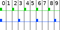
Above, you can see example using of values 2 and 3.
Greatest Common Divisor is 1 (size of 1 column).
Least Common Multiple is 6 (repetitive timing).
Safety Shutdown
"Safety Shutdown" can be two things.It may be hardware button button hidden under fur to retract wings without communication with Central Unit.
Second meaning is checking voltage of battery and when it reaches too low, retract wings while we are able to do so.
Analog Pins as Digital
Because we have already filled all 14 (0-13) digital pins:-
0 to 1 (2)
Serial Port -
2 to 5 (4)
Stepper Motor for first wing -
6 to 7 (2)
Limits for first wing -
8 to 11 (4)
Stepper Motor for second wing -
12 to 13 (2)
Limits for second wing
It is same as working with Digital Pins (0 - 13) but we must prefix it by A (A0 - A5).
Hardware Shutdown
It is important to have a way to shutdown (retract) wings. Why? Because anything can happen and we may need to retract them.One of them may be not having it on fursuiter's input. Another may be problem in Central Unit (or between it and Stepper Motors).
I decided to place small microswitch under fur but I am still not sure where to place it.
First idea is to place it between wings. Its advantage is distance because it does not require any connector which may need to be used when putting the suit on.
Second idea is to place it on head. More specifically on top edge of snout (hidden under fur) or behind nose (reacting on nose touch / press).
In any way, it will be a switch and while pressed, the wings should retract and stay retracted.
#define PIN_SHUTDOWN A0pinMode(PIN_SHUTDOWN, INPUT_PULLUP);We define the pin...
  if(digitalRead(PIN_SHUTDOWN) == LOW)
  {
    left_changeTargetStep(0.0f);
    right_changeTargetStep(0.0f);
    while(!left_done || !right_done)
    {
      left_performStep();
      right_performStep();
      // 2000 rotations per 1s
      delayMicroseconds(500);
    }
  }
...and mostly use the code from Reset Position on Start...
    delay(1000);
    return;
...but we also add delay after retracting wings (end of condition block) to keep them retracted. This whole condition should be placed at beginning of
loop() function to prevent rest of the code from executing when the "Shutdown Button" is pressed.
Low Battery Shutdown
Because Power Preprocessor is already prepared for voltage monitor from Central Unit, we only need to fork it and use same code.#define PIN_VOLTAGE A1#define VOLTAGE_SHUTDOWN if((analogRead(PIN_VOLTAGE) / 1024.0f) * 20 < VOLTAGE_SHUTDOWN)
{
}Analog to Digital conversion takes about 100µs (~10,000 times per second) so it can mess with our timing.
  if(left_done && right_done)
  {

  }
We should only check it when not controlling motors.
#define VOLTAGE_CHECK 40
int voltage_check_step = 0;
if(voltage_check_step == VOLTAGE_CHECK)
{
}
voltage_check_step++;And only few cycles (~few seconds).
    delay(100);
    return;
We also add 100ms (0.1s) delay to save batteries.